


How to Get Your IoT Product Certified at Minimum Cost
The challenges in bringing an IoT product to the market extends beyond the design. The next critical step — product certification — becomes a showstopper for many projects. The perception of hardware commoditization forces many IoT designers to use off-the-shelf modules and antennas in their projects with connectivity via LoRa, Cellular (NB-IoT, Cat-M1, 2G, 3G, 4G or 5G), Sigfox, Bluetooth, subGHz, Weightless, Wi-Fi, WirelessHART, Zigbee, Z-Wave and many more.
How can you expect to solve certification issues?
I have a simple question for IoT designers. When you don’t control anything in your design-yielding to plug and play available solutions–how can you expect to solve certification issues? Take note that neither the module manufactures, nor the antenna manufacturers will guarantee that your embedded/IoT designs will be certifiable.
Certification test varies based on product region of use, product type and so on. For example, wearable and portable products have stringent certification requirement as compared to fixed (immovable) products. If your product is wearable and it only passes FCC-SAR at a 10 cm distance, it means that the customer should use the device at a 10 cm distance. Due to this, it’s impossible to use the product as a wearable! Moreover, cellular products have stringent certification requirements compared to all other wireless technologies due to the Global Certification Forum (GCF) and PCS Type Certification Review Board (PTCRB) requirements. Using off-the-shelf cellular modems paired with off-the-shelf antennas will fail GCF or PTCRB certification especially OTA (TRP, TIS) and Radiated Spurious Emissions (RSE) tests.
Certification is not something which comes at the end of the product development but needs to be taken into account at every stage of product development. If we design products with certification in mind, we can avoid overspending at the certification lab trying to resolve the certification issues because certification labs are very costly.
I often get asked this same question in various ways: “The module is certified, and the antenna is tested, why won’t it pass the certification?”.
Here’s why products won’t pass the certification:
- The performance of the radio module tends to vary due to the tolerance of the RF components. Due to this variation, the RF performance of one module will be slightly different from another. Your radio module could be performing at the lower end of the spec which could lead to certification issues for your IoT product.
- The off-the-shelf antennas are often designed to perform at a frequency band of interest and not designed for a good suppression of out of band frequencies especially 2nd harmonics, intermodulation emissions, noise, and spurs. Antenna tunning to suppress second harmonics is something which all the IoT product designers have to do before going to the certification lab. It can even be done for off-the-shelf antennas via impedance matching network.
- Poor PCB board design could lead to multiple unsolvable certification issues. Integrating multiple radio modules into a product or integrating a single radio and multiple sensors into a product may create unwanted spurious issues due to the crystal oscillator’s noise and the coupling between noisy traces and components. Noise, intermodulation emission, and spurs will results in RSE test failure during certification. Most product designers will only discover this issue at the certification lab. However, good designers will predict the problem via EMC/EMI simulation using CAD simulation tools such as Keysight ADS, CST, ANSYS and so forth and fix it in the design stage.
- Before doing the Specific Absorption Rate (SAR) test, you are required to do conducted power measurement at SAR test lab. The measured conducted power of the module must be within the upper and lower power specification given in the module datasheet. Most of the suppliers will have a UFL connector on their module and conducted power will be measured via the UFL connector. Don’t be surprised that your module might fail the SAR conducted power test. The module underperforming and contradicting its own datasheet can never be your fault but it has happened many times before! Some module suppliers will be willing to correct their datasheet or tune-up the module power. However, they might also just ignore you because you are just one in a million customers to them. If you would have tested the conducted power at your lab and made sure it’s meeting its own datasheet at the development stage, it could have saved a lot of hassle and money during certification.
- PTCRB-OTA (TRP and TIS ) is one of the hardest tests to pass for cellular devices. The product has to meet the lower limit of the radiated power level. If your device is small and your cellular (NB-IoT,Cat-M1, 2G, 3G, 4G or 5G) antenna doesn’t have enough ground plane length to radiate efficiently, it will fail this test. If you just fail one channel with a very small margin, you can write to your cell service provider for the waiver. However, if its failing multiple channels, you need to fix your antenna to pass the test.
- PTCRB-RSE is another cellular certification test with a stringent requirement. As compared to FCC-RSE which has a limit of -13 dBm, PTCRB-RSE has a limit of -30 dBm which is harder to meet for many products at 2nd harmonics. The cellular modem will not guarantee lower second harmonics to pass this test and in most cases, it will fail the test! Antenna tuning is the only solution to contain this and it can be done during the development stage.
All the issues I have given above are severe issues faced by many companies during product certification. It doesn’t mean that the rest of the certification tests are easy to pass. Poor design can lead to many more failures during the certification which can cost companies a lot of money.
Product certification failure
Certification failures will be reflected by the product’s poor performance in the field. I have seen many IoT designers encountering huge certification issues after completing the design and marketing for their products. In most cases, parts or layout must be re-designed to solve these certification issues. It will cost way more to solve the certification issues at the certification lab because certification labs often charge their customers by the minute!
Product certification examples
The image below is an example of Innowave’s custom-designed 3G antenna. This antenna is designed for a dual-band cellular modem with frequency bands of EGPRS850, EGPRS1900, WCDMA850 and WCDMA1900. Moreover, we designed and certified this product. This product is FCC, PTCRB and AT&T certified. Figure 1 shows the input impedance measurement of the dual-band cellular antenna.
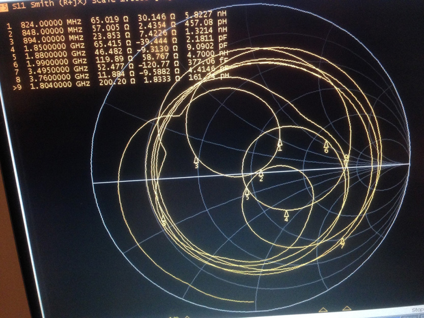
Figure 1. The matched Input Impedance of the dual-band cellular antenna
Figure 2 shows the return loss of the dual-band antenna. The antenna is meeting specifications at the frequency band of interest and also has good harmonic suppression at 2nd harmonic frequencies.
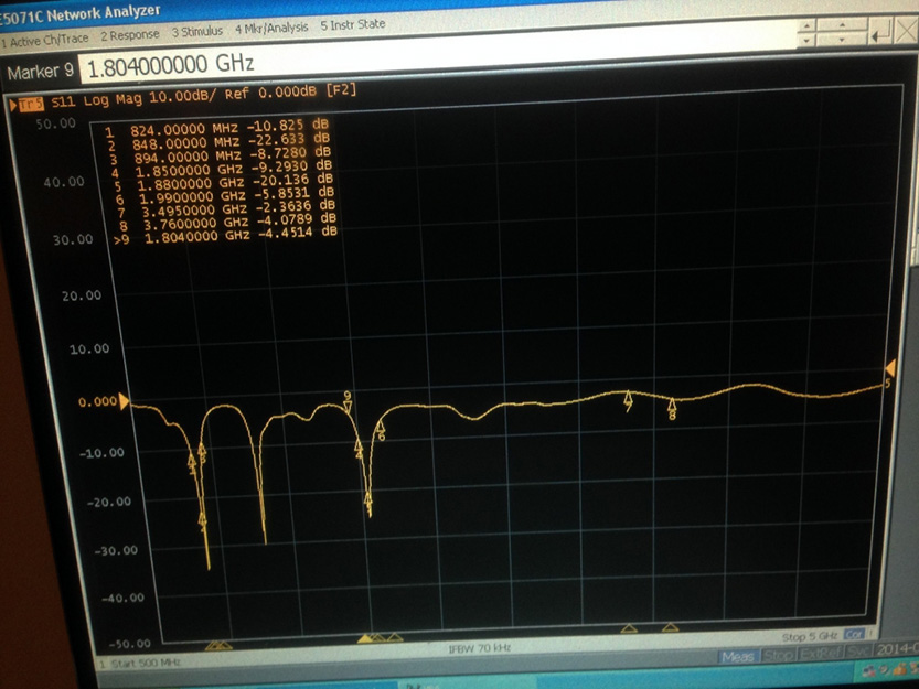
Figure 2. Return loss of dual-band cellular antenna.
Figure 3 shows the antenna’s total efficiency measurement at the low band (824 MHz – 894 MHz). The graph was plotted across 700 MHz to 1.2 GHz to give an overall picture of the low frequency. Good low band efficiency (> 40 %) has made the product passes PTCRB-OTA tests at 850 band. Moreover, the modem supports 900 band as well. Low efficiency at 900 band is needed to avoid PTCRB-RSE problems at the second harmonics of 900 band. Figure 3 shows low efficiency at 900 band (880 MHz – 960 MHz) which guarantees no issues for PTRCB-RSE at 900 band.
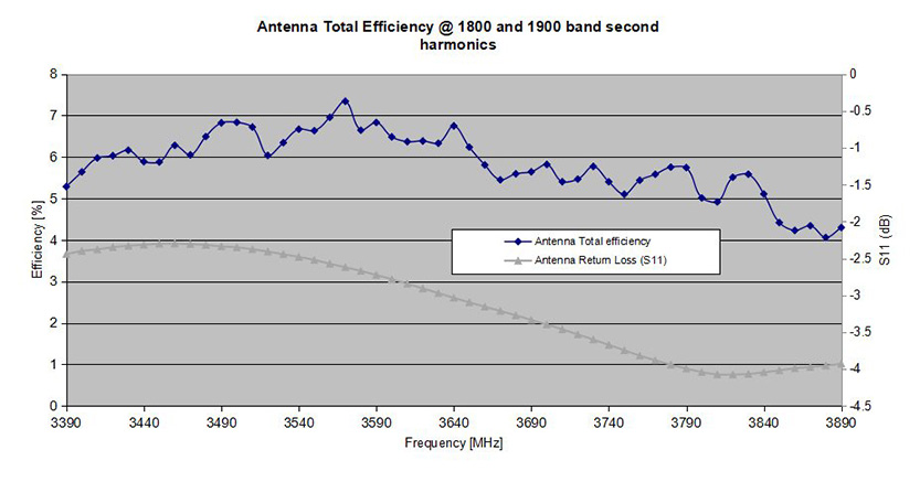
Figure 3. Antenna Total Efficiency at Low band (850 Band)
Figure 4 shows the antenna’s total efficiency measurement at the high band (1850 MHz – 1990 MHz). The graph was plotted across 1570 MHz to 2.07 GHz because 2nd harmonics of 900 band and 850 band are 1760 MHz to 1920 MHz and 1640 MHz to 1800 MHz respectively. Even though the product is only certified for the US (850 and 1900 band) only, since the modem supports 900 and 1800 band, PTCRB-RSE will be tested for these bands as well. Good 1900 band efficiency (> 40 %) has made the product passes PTCRB-OTA at 1900 band whereas low 2nd harmonic efficiency of 900 and 850 bands have made the product passes PTCRB-RSE for 900 and 850 bands.
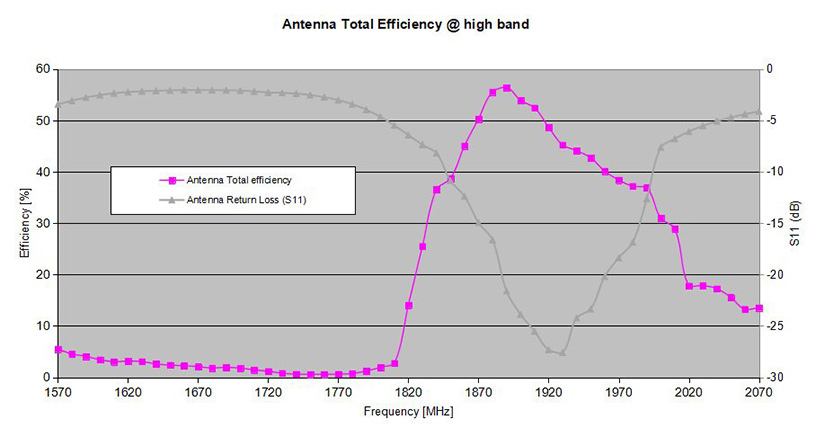
Figure 4: Antenna Total Efficiency at High Band (1900 Band) and 2nd harmonics of 900 band 850 bands.
Figure 5 shows Total efficiency at the second harmonics of 1800 and 1900 band which are 3420 MHz to 3760 MHz and 3700 MHz to 3980 MHz respectively. Low second harmonic efficiency (4 – 7 %) has made the product passes PTCRB-RSE for 1800 and 1900 band.
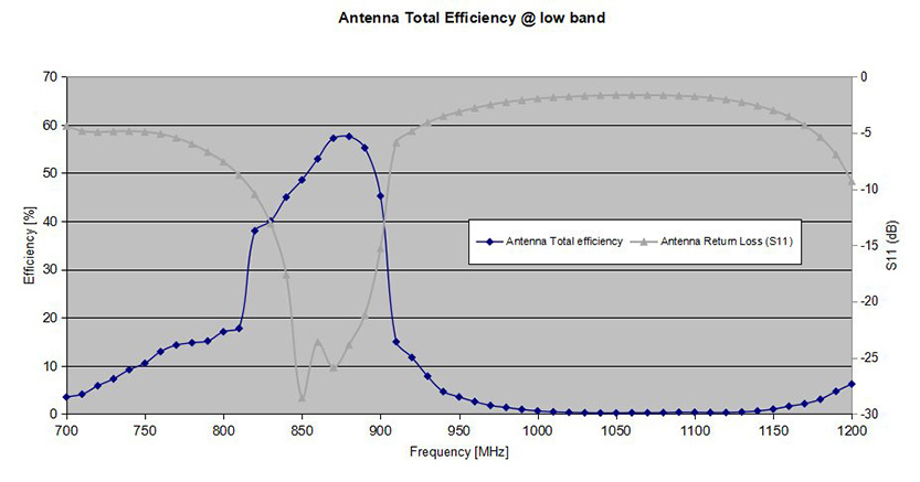
Figure 5: Antenna Total Efficiency at second harmonics of 1800 and 1900 band.
In Figure 3, 4 and 5, measured efficiency together with measured return loss (S11) at Cetecom Milpitas.
Originally this article was published here.
![]() This article was writteh by Pragash Sangaran, the Co-Founder and Director of Innowave LLC. He holds a Ph.D. in RF and Microwave Engineering and has more than fourteen years of experience in hardware, RF transceiver and embedded product design as well as product certification.
This article was writteh by Pragash Sangaran, the Co-Founder and Director of Innowave LLC. He holds a Ph.D. in RF and Microwave Engineering and has more than fourteen years of experience in hardware, RF transceiver and embedded product design as well as product certification.

Is that Newborn an IoT or an IIoT – How to Decide?
Introduction During the past decades, we learned about Information Technology (IT), Industrial Control Systems (ICS), Operation Technology (OT), and Supervisory Control and Data Acquisition (SCADA) systems, which manage the operation of a broad range of consumer, commercial industrial and more

IoT in fleet management: enhancing efficiency, sustainability, and safety
The expanding global adoption of IoT technology has unlocked many opportunities for businesses in the automotive domain, from optimized car manufacturing processes to autonomous vehicles and usage-based insurance. The IoT for automotive has also influenced how transportation companies operate and

Dive into the Future: A 5-Day IoT Security Webinar Series
Embark on a deep exploration of the Internet of Things (IoT) with Keyfactor's upcoming 5-day webinar series, "IoT Insights Unveiled: A 5-Part Webinar Series”. The series will focus on IoT Security. Event Details: • Series Title: IoT Insights Unveiled: A 5-Part Webinar